Charging guide: Choosing a Charging station
The choice of a charging station depends on your electrical grid and the size of your main intake fuse / main fuse, and how much of this you can allocate to the charging station(s).
What power grids are available?
These are mainly two different types of power grids.
IT (Isolated Terra) is found in approximately 75 per cent of in Norway, and consists of either 1-phase (2 conductors) or 3-phase (3 conductors) plus earth (PE). There is 230V between each of the conductors and the neutral point of the transformer is not earthed, but is protected with a spark gap between neutral point and earth. Thus, there is no so-called zero conductor. To convert from IT to TN, a transformer must be used.
TN (Terra neutral) is used in almost all of Europe, and around 25 per cent of Norwegian electricity subscribers have this. TN consists of four conductors (three phase conductors and one neutral conductor) plus earth (PE). This means that you can extract 230V between each of each phase conductor and neutral conductor, and you get 400V between each phase conductor.
Do I have an IT- or a TN- power grid?
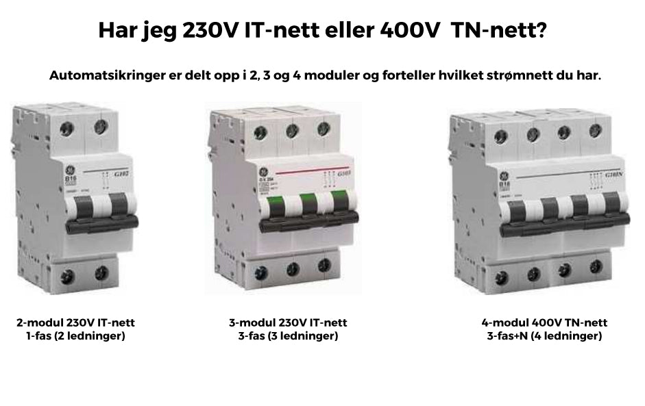
If there is not a sticker with e.g. "IT" (230V), "TN-C" (400V) or "TN-S" (400V) on the fuse box you are going to draw the power from, you can check the input fuse / circuit breakers.
How large a current rate can I get?
Once you have first found out which power grid you have, you must find out how big a power rate you have the capacity to put forward. If you are not absolutely sure that you have sufficient capacity, we would recommend that you call an electrician for an inspection or send us a photo of the fuse box and course list. Most people will normally be able to present a minimum of one 16A current course. A future-oriented thought is also to invest in a 32A charging station that can be adjusted to 16A or the desired amperage, and thus you have the option of adapting the charging station to the current rate that can be presented from the fuse box. All our 32A charging stations are adjustable down to 16A and can thus be used at both 32A and 16A.
Newer smart charging stations now have the option of dynamic charging that adapts to the consumption in the house and thus everyone can get up to 32A charging as long as one has a main fuse of 40A or more. If you choose such a charging station, you will automatically be able to get maximum speed as long as the current rate is 32A.
What current rate and number of phases should I choose?
It is recommended to submit the largest possible current rate to the charging station(s) that the capacity allows and the highest number of phases that are available. In other words, if you have the option for 32A, 3-phase (either 230V or 400V), then put this forward from the fuse box. Even if your current car e.g. only supports 1-phase, so it is more forward-looking to present a 3-phase solution if you have this available. At the same time, the probability that your next car will be able to support several phases is high and thus provide the opportunity for faster charging. A charging station marked with 400V/3-phase (TN) is compatible with IT networks and can be installed on 230V 1- and 3-phase power networks (IT).
What is 1-phase, 2-phase and 3-phase?
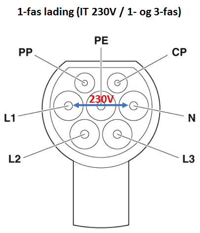
1) 1-phase connection is a connection between the N conductor and one phase conductor, either L1, L2 or L3 and provides 230V in a TN network (400V). In a 230V IT network, 1-phase connection is between two phase conductors and these are still connected L1 and N.
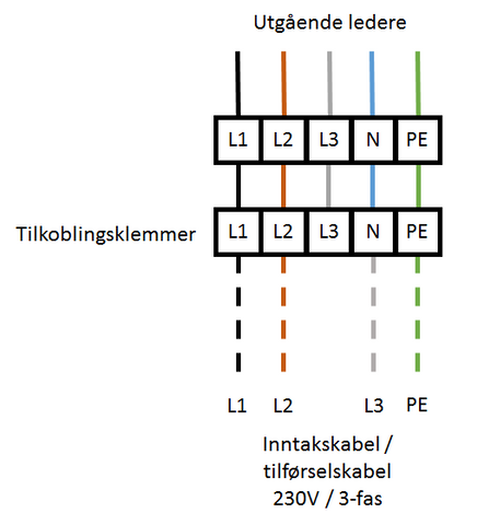
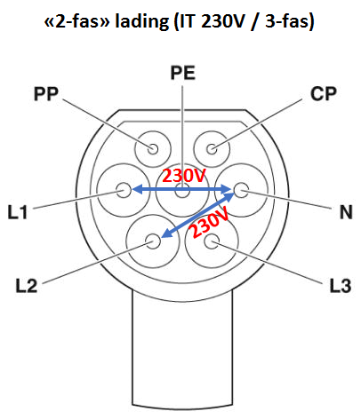
2) A so-called "2-phase" connection is the connection between L1, L2 and L3 in an IT network (230V) to respectively L1, L2 and N in a 400V charging station. Below we have illustrated a "2-phase" connection of a charging station which is designed for 400V / 3-phase (TN), but is connected to 230V / 3-phase (IT).
 |
 |
3) In a TN network, you can draw 3-phase in two ways:
3a) Delta load: connection between L1-L2-L3 which provides 400V between the phase conductors.
3b) Star load: connection between N conductor to L1, L2 and L3, respectively, which provides 230V between phase conductor and N.
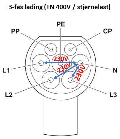
Charging of electric vehicles in a 400V TN network is done with a star load as illustrated in the picture above.
The table below shows an overview of the number of phase conductors, N conductor and earth at TN and IT networks.
| Pkt. | Power Grid | Voltage | Connection | L1 | L2 | L3 | N-conductor | PE (ground) |
|---|---|---|---|---|---|---|---|---|
| 1) | TN | 230V | 1-phase | X | X | X | ||
| 1) | IT | 230V | 1-phase | X | X | X | ||
| 2) | IT | 230V | 2/3-phase | X | X | X | X | |
| 3a) | TN | 400V | 3-phase | X | X | X | X | |
| 3b) | TN | 230V | 3-phase | X | X | X | X | X |
Do you need advice regarding the installation of a charging station or charging point? Check our installation guide here.
 FedEx delivery in the EU
